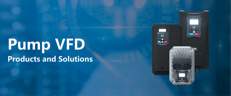

Pump inverters (0.4 kW -400 kW) with protection degree from IP20 to IP67

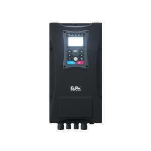
Pump inverters (0.4 kW -11 kW) with protection degree from IP20 to IP67

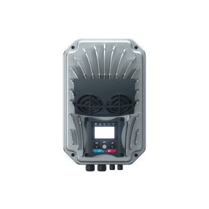
Pump inverters (0.4 kW -90 kW) with protection degree from IP20 to IP67
| Model No. | EP66P |
|---|---|
| Rated input voltage | 3-Phase 380V-460V (+/-15%) 3-phase 220V-240V(+/-15%) 1-Phase 220V~240V (+/-15%) |
| Input frequency | 44….67 Hz |
| EMC Filter | Integrated C3 class filter as standard (industrial area) (optional internal C1 class filter kit available) |
| Output voltage | 0………V-input |
| Output frequency | 0………650 Hz (1500Hz option) |
| Frequency resolution | 0,01 Hz |
| Overload capability | 150% – 60 sec. / 10 min |
| Motor control algorithm | V/Hz-SpaceVector, SLV-Sensorless Vector control, Torque/Speed control mode, CLV-Closed loop vector, PMSM Sensorless control |
| Chopper frequency | 0.8…16 kHz (fixed / random) |
| V/Hz curve | Linear, exponential, and user-programmable curve |
| Starting torque | 150% rated torque at 0.5 Hz (in SLV Mode) |
| Torque compensation | Automatic / Manual |
| Motor data input | Manual, from nameplate / AUTOTUNING |
| Control range | 1:100 in SLV mode, 1:1000 in CLV mode, 1:20 in PMSM mode |
| Speed precision | +/- 0,5% (SLV), +/- 0.02% (CLV) |
| Torque precision | +/- 5% (SLV) |
| DC-Brake | Programmable in duration and intensity |
| Brake chopper | Chopper transistor integrated |
| 4 Line character display | Displays configuration parameters, inverter status and operating parameters – programmable, easy and flexible |
| Inverter control | Via terminals / Keypad / Serial link (or combination) |
| Digital inputs | 6 (8) digital inputs (NPN-PNP selectable) pulstrain-input |
| Speed reference input | Potentiometer, analogue signal (terminals), keypad (INC/DEC), pulsetrain, via serial link |
| Analogue channels | 2 analogue inputs – 12 BIT: 0…10V, 0…5V, -10V…0…10V, 0..(4)20 mA, scalable in gain and offset |
| Analogue outputs | 1 (2) analogue outputs, programmable in gain and function (0…10V, 0(4)..20 mA) |
| Digital outputs | 1 (2) digital OC outputs (free mapping to different functions) |
| Relais output | 1 switchover contact 5 A 230 V (programmable) |
| Data link | Serial link RS 485 (MODBUS ASCII/RTU) |
| Special functions | 24V / 50 mA auxiliary power supply on terminals, 10V potentiometer powersupply, 5V/100 mA power supply on modbus connector Simple PTC / KLIXON motor protection |
| Electronic protections – Thermal | Over-voltage, under-voltage, over-current, overload |
| Electronic protections – Display | Inverter overtemperature, I²xt motor protection PTC/LIXON read in |
| Display | IP66 Remote display / keypad unit |
| Dynamic brake | Braking resistors for different load characteristics |
| Power control options | Main switch, emergency switch, BYPASS switch |
| Inverter control options | Potentiometer, inverter control selector switches |
| PC-software / Parameter Stick | Configuration, control, diagnosis tool, Parameter copy/duplicating stick |
| Protection class | IP66 / NEMA4 |
| Operating temperature | -10……+40 °C (-40 with optional antifreeze control) |
| Humidity | 0 to 98% non-corrosive |
| Altitude | 1000 m, above 1% derating / 100m |
| Vibration | Max. 1,0 g |
| Power range | 0,4……90 kW |
| Electromagnetic compatibility | EN61800-3(2004) |
| Safety | EN61800-5-1 2003 |
| Model No. | EM30P |
|---|---|
| Rated input voltage | 3-Phase 380V-460V (+/-15%) 1-Phase 220V~240V(±15%) 3-Phase 220V~240V(±15%) |
| Input frequency | 44….67 Hz |
| EMC filter | Integrated for industrial area (optional for residential area) |
| Output voltage | 0………V-input |
| Output frequency | 0………650 Hz (1500Hz option) |
| Frequency resolution | 0,01 Hz |
| Overload capability | 150% – 60 sec. / 10 min |
| Motor control algorithm | V/Hz-SpaceVector, SLV-SENSORLESS VECTOR, Torque/Speed control mode CLV Closed loop vector, Permanent Magnet Synchronous Motor PMSM SENSORLESS control |
| Chopper frequency | 0.8…16 kHz (fixed / random) |
| V/Hz curve | Linear, exponential, and user-programmable curve |
| Starting torque | 150% rated torque at 0,5 Hz (in SLV Mode) |
| Torque compensation | Automatic / Manual |
| Motor data input | Manual, from nameplate / AUTOTUNING |
| Control range | 1:100 in SLV mode, 1:1000 in CLV mode, 1:20 in PMSM mode |
| Speed precision | +/- 0,5% (SLV), +/- 0.02% (CLV) |
| Torque precision | +/- 5% (SLV) |
| DC-Brake | User programmable functions |
| Brake chopper | Chopper transistor integrated (up to 22 kW) |
| 4 Line Character display | Config-Parameters and -value, programmable to display various working parameters |
| Analogue channels | 2 analogue channels – 12 BIT: 0…10V, 0…5V, -10V…0…10V, 0..(4)20 mA, scalable in gain and offset |
| Analogue outputs | 2 analogue outputs, programmable in gain and function (0…10V, 0(4)..20 mA) |
| Digital outputs | 2 relais with switchover contacts 5A 230V capability |
| Data link | Serial link RS 485 (MODBUS) |
| Special functions | 24V / 200 mA auxiliary power supply on terminals, 10V potentiometer power supply, 5V/100 mA power supply on modbus connector PTC / KLIXON motor protection |
| Electrical | Overvoltage, undervoltage, Overcurrent, overload, motor-overload, output short-circuit, Input phaseloss, motor phase unbalance |
| Thermal | Heatsink overtemperature, I2xt motor protection |
| Display | Remotable display / keypad units |
| Brake chopper | Braking resistors for different load characteristics |
| PC-software Parameter copy stick | Configuration, control, and diagnosis tool, parameter copy/duplicating stick |
| Protection class | IP66 / NEMA4 motor/wall mountable |
| Operating temperature | -10……+40 °C – -40°C with automatic antifreeze control (option) |
| Humidity | 0 to 95% RH, non-condensing, non-corrosive |
| Altitude | 1000 m, above 1% derating / 100m |
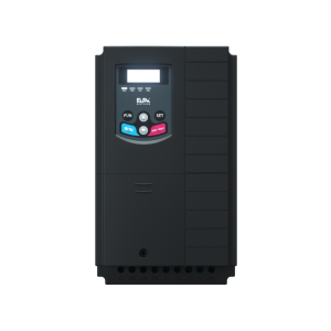
| Model No. | E2100P |
|---|---|
| Rated input voltage | 3-phase 380-480V (+10%, -15%) note 1 3-phase 220V~240V ±15% 1-phase 220-240V ±15% |
| Rated Input frequency | 50/60Hz |
| Rated Output Voltage Range | 3-phase 0-INPUT (V) |
| Frequency Range | 0.50–590.0Hz (In SVC control mode, the max frequency should be lower than 500Hz.) |
| Carrier Frequency | 800–16000Hz; Fixed carrier-wave and random carrier-wave can be selected by F159. |
| Input Frequency Resolution | Digital setting: 0.01Hz, analog setting: max frequency × 0.1% |
| Control Mode | For induction motor: SVC (open-loop vector control), V/F control, VC (Closed-loop vector control) For PMSM: SVC (open-loop vector control) |
| Start Torque | 0.5 Hz / 150% (SVC), 0Hz / 180% (VC), 5% of rated speed / 100% of rated torque (PMSM SVC) |
| Speed-control Scope | 1:100 (SVC), 1:1000 (VC), 1:20 (PMSM SVC) |
| Steady Speed Precision | ±0.5% (SVC), ±0.02% (VC) |
| Torque Control Precision | ±5% |
| Overload Capacity | 150% rated current, 60 seconds |
| Torque Elevating | Auto torque promotion, Manual Torque Promotion includes 1–20 curves |
| V/F Curve | 3 kinds of modes: beeline type, square type, and under-defined V/F curve |
| Startup mode | Direct startup, speed track startup (V/F control) |
| DC Braking | DC braking frequency: 0.20–50.00 Hz, braking time: 0.00–30.00s |
| Jogging Control | Jogging frequency range: min–max frequency, jogging acceleration/deceleration time: 0.1–3000s |
| Auto Circulating Running and multi-stage speed running | Auto circulating running or terminals control can realize 15-stage speed running |
| Built-in PID adjusting | Easy to realize a system for process closed-loop control |
| Auto voltage regulation (AVR) | When the source voltage changes, the modulation rate can be adjusted automatically so output voltage is unchanged |
| Frequency Setting | Potentiometer or external analog signal (0–5V, 0–10V, 0–20mA); keypad (terminal) ▲ ▼ keys, external control logic, and automatic circulation setting |
| Start/Stop Control | Terminal control, keypad control, or communication control |
| Running Command Channels | 3 channels: keypad panel, control terminal, MODBUS |
| Frequency Source | Given digit, given analog voltage, given analog current, and MODBUS |
| Accessorial frequency Source | 7 kinds of accessorial frequency |
| Optional | Built-in EMI filter, built-in braking unit, Modbus, tele-control panel |
| Protection Function | Input phase loss, Output phase loss, input under-voltage, DC over-voltage, over-current, inverter over-load, motor over-load, current stall, over-heat, external disturbance, under-load, pressure control, analog line disconnected, PG line disconnection, keypad disconnection, Open protection, STO and STO1 |
| Display | Keypad showing present output frequency, rotation speed (rpm), output current, output voltage, linear velocity, types of faults, and system parameters; LED indicators showing working status |
| Environment Conditions – Equipment Location | Indoor, prevent direct sunlight, free from dust, corrosive gases, flammable gases, steam, or salt content |
| Environment Temperature | -10 °C ~ +50° C |
| Environment Humidity | Below 90% (no water-bead coagulation) |
| Vibration Strength | Below 0.5g (acceleration) |
| Height above sea level | 1000m or below |
| Protection Level | IP20 |
| Applicable Motor | 0.2–400kW |