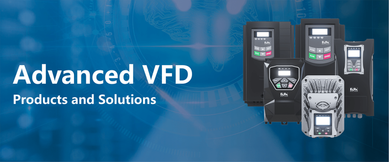
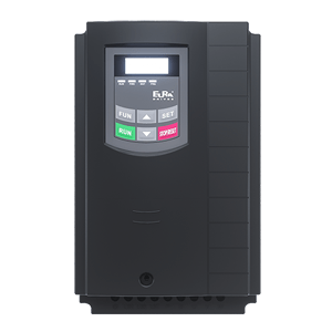
High-tech motor control based on advanced DSP-technology
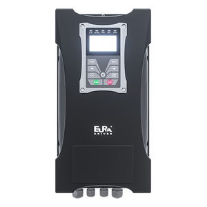
DSP based high-tech motor control
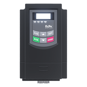
The inverter for HVAC applications – compact, low cost and reliable
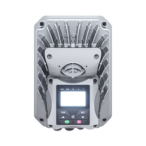
High-tech motor control based on advanced DSP- technology V/Hz
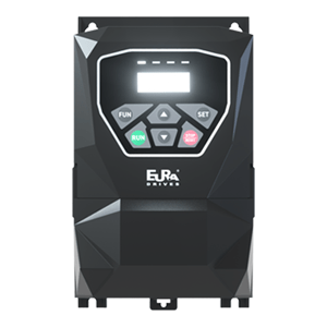
Best performance/cost ratio, without compromise in reliability and quality
| Model No. | E2100 |
|---|---|
| Rated input voltage | 3-Phase 380V-460V (+/-)15% 1-Phase 220V~240V(±15%) |
| Input frequency | 44….67 Hz |
| EMC Filter | Integrated for 2. environment – industrial area (optional for residential area) |
| Output voltage | 0………V-input |
| Output frequency | 0………650 Hz (1500HZ OPTION) |
| Frequency resolution | 0,01 Hz |
| Overload capability | 150% – 60 sec. / 10 min |
| Motor control algorithm | V/Hz-SpaceVector, SLV-SENSORLESS VECTOR, Torque/Speed control mode CLV-Closed loop vector, Permanent Magnet Synchronous Motor PMSM SENSORLESS control |
| Chopper frequency | 0.8…16 kHz (?xed / random) |
| V/Hz curve | Linear, exponential, and user-programmable curve |
| Starting torque | 150% rated torque at 0,5 Hz (in SLV Mode) |
| Torque compensation | Automatic / Manual |
| Motor data input | Manual, from nameplate / AUTOTUNING |
| Control range | 1:100 in SLV mode, 1:1000 in CLV mode, 1:20 in PMSM mode |
| Speed precision | +/- 0,5% (SLV), +/- 0.02% (CLV) |
| Torque precision | +/- 5% (SLV) |
| DC-Brake | User programmable functions |
| Brake chopper | Chopper transistor integrated (up to 90 kW) |
| Display 7 segment, 4 characters | Config-Parameters and -value, programmable to display various working parameters |
| Inverter control | Via terminals / Keypad / Serial link (or combination of all) |
| Digital inputs | 6 (8) Dig. inputs (NPN-PNP selectable) pulstrain-input |
| Speed reference input | Potentiometer (on keypad unit, external), analogue signal (terminals), keypad, internal programmable value, pulsetrain, serial link |
| Analogue channels | 2 analogue channels – 12 BIT: 0…10V, 0…5V, -10V…0…10V, 0..(4)20 mA, all free scalable in gain and offset, and mathematically concatenable |
| Analogue outputs | 2 analogue outputs, programmable in gain and function (0…10V, 0(4)..20 mA) |
| Digital outputs | 2 digital outputs (free mapping to different functions) |
| Relais output | 1 switchover contact 3A 250VAC/30VDC (programmable assignment) |
| Data link | Serial link RS 485 (MODBUS) |
| Special functions | 24V / 50 mA auxiliary power supply on terminals, 10V potentiometer power supply, 5V/100 mA power supply on modbus connector, Simple PTC / KLIXON motor protection |
| Electronic protections with fault history | Overvoltage, undervoltage, Overcurrent, overload, motor-overload, output short-circuit |
| Thermal | Heatsink overtemperature, I2xt motor protection |
| Display | Remotable display / keypad units |
| Brake chopper | Braking resistors for different load characteristics |
| PC-software Parameter Stick | Configuration-, control- and diagnosis-tools, parameter duplicating stick, IP66 remote keypad with 4 line character display |
| Protection class | IP20 / IP21 (optional) |
| Working temperature | -10……+50 °C |
| Humidity | 0 to 95% RH, non-condensing, non-corrosive |
| Altitude | 1000 m, above 1% derating / 100m |
| Vibration | Max. 0,5 g |
| Power range | 0,4……400 kW |
| Electromagnetic compatibility | EN61800-3(2004) |
| Safety | EN61800-5-1 2003 |
| Model No. | EP66 |
|---|---|
| Rated input voltage | 3-Phase 380V-460V (+/-15%) 3-phase 220V-240V(+/-15%) 1-Phase 220V~240V (+/-15%) |
| Input frequency | 44….67 Hz |
| EMC Filter | Integrated C3 class filter as standard (2. environment – industrial area) (optional internal C1 class filter kit available) |
| Output voltage | 0………V-input |
| Output frequency | 0………650 Hz (1500HZ OPTION) |
| Frequency resolution | 0,01 Hz |
| Overload capability | 150% – 60 sec. / 10 min |
| Motor control algorithm | V/Hz-SpaceVector, SLV-SENSORLESS Vector control, Torque/Speed control mode CLV-Closed loop vector, PMSM Permanent Magnet Synchronous Motor SENSORLESS control |
| Chopper frequency | 0.8…16 kHz (fixed / random) |
| V/Hz curve | Linear, exponential, and user-programmable curve |
| Starting torque | 150% rated torque at 0,5 Hz (in SLV Mode) |
| Torque compensation | Automatic / Manual |
| Motor data input | Manual, from nameplate / AUTOTUNING |
| Control range | 1:100 in SLV mode, 1:1000 in CLV mode, 1:20 in PMSM mode |
| Speed precision | +/- 0,5% (SLV), +/- 0.02% (CLV) |
| Torque precision | +/- 5% (SLV) |
| DC-Brake | Programmable in duration and intensity |
| Brake chopper | Chopper transistor integrated |
| 4 Line character display | To display configuration parameters, Inverter status and various operating parameters – all programmable, easy and flexible |
| Inverter control | Via terminals / Keypad / Serial link (or combination of all) |
| Digital inputs | 6 (8) Dig. inputs (NPN-PNP selectable) pulstrain-input |
| Speed reference input | Potentiometer, analogue signal (terminals), keypad (INC/DEC), pulsetrain, via serial link |
| Analogue channels | 2 analogue inputs – 12 BIT: 0…10V, 0…5V, -10V…0…10V, 0..(4)20 mA, all free scalable in gain and offset, and mathematically concatenable |
| Analogue outputs | 1 (2) analogue outputs, programmable in gain and function (0…10V, 0(4)..20 mA) |
| Digital outputs | 1 (2) digital OC outputs (free mapping to different functions) |
| Relais output | 1 switchover contact 5 A 230 V (programmable function assignment) |
| Data link | Serial link RS 485 (MODBUS ASCI/RTU) |
| Special functions | 24V / 50 mA auxiliary power supply on terminals, 10V potentiometer power supply, 5V/100 mA power supply on modbus connector Simple PTC / KLIXON motor protection |
| Electronic protections with fault history – Thermal | Over-voltage, under-voltage, over-current, overload |
| Electronic protections with fault history – Display | Inverter overtemperature, I²xt motor protection, PTC/KLIXON read in |
| Display | IP66 Remote display / keypad unit |
| Dynamic brake | Braking resistors for different load characteristics |
| Power control options | Main switch, emergency switch, BYPASS switch |
| Inverter control options | Potentiometer, inverter control selector switches |
| PC-software / Parameter Stick | Configuration-, control- and diagnosis-tool, Parameter copy/duplicating stick |
| Protection class | IP66 / NEMA4 |
| Operating temperature | -10……+40 °C (-40 with optional antifreeze control) |
| Humidity | 0 to 98% non-corrosive |
| Altitude | 1000 m, above 1% derating / 100m |
| Vibration | Max. 1,0 g |
| Power range | 0,4……90 kW |
| Electromagnetic compatibility | EN61800-3(2004) |
| Safety | EN61800-5-1 2003 |
| Model No. | E800 |
|---|---|
| Supply voltage | Phase 220V ~240V (+/-15%) 3-Phase 380V-460 (+/-15%) |
| Input frequency | 44….67 Hz |
| EMC Filter | Integrated for second environment (industrial area) – option for first environment (residential area) |
| Output voltage | 0………V-input |
| Output frequency | 0.5………650 Hz |
| Overload capability | 120% – 60 sec / 15 min |
| Control Mode V/Hz | Linear, Variable torque curve, user programmable curve |
| PWM frequency | 800…10000Hz (FIXED / RANDOM) |
| Display LED 7-segment display | Programmable, to display various inverter and working parameters |
| Digital inputs | 6(8) dig. inputs (PNP/NPN) |
| Analog inputs | 2 x 12 BIT analogue inputs 0…10V, 0(4)…20 mA |
| Analog outputs | 2 analogue outputs, to assign to various functions (0…10V, 0…20 mA) |
| Digital outputs | 2 digital outputs (free assignment to different functions) |
| Relais | 1 switchover contact 5 A 230 V (programmable function) |
| MODBUS | Inverter control, reading and setting of all inverter I/O channels |
| Aux. power supply | Auxiliary power supply: 24V / 50 mA – on terminals, 10V potentiometer power supply |
| Electrical protections | Overvoltage, undervoltage Overcurrent, overload, motor overload, short circuit |
| Thermal protections | Inverter overtemperature, motor-overload I²xt |
| Display / keypad | Remote display / keypad unit |
| Brake | Brake resistors for all kinds of applications |
| PC-Link Software | Smart tool for parameter setting, control and diagnosis |
| Fieldbus | Gateway modules for all commonly used bus technologies |
| Parameter copy stick | Smart tool for parameter storage and duplication |
| Protection degree | IP20 / IP21 (option) |
| Operating temperature | -10……+40 °C |
| Humidity | Max. 90 % non-condensing, non-corrosive |
| Altitude | 1000 m, above derating of 1% / 100m |
| Model No. | EM30 |
|---|---|
| Rated input voltage | 3-Phase 380V-460V (+/-15%) 1-Phase 220V~240V(±15%) 3-Phase 220V~240V(±15%) |
| Input frequency | 44….67 Hz |
| EMC filter | Integrated for 2. environment – industrial area (optional for residential area) |
| Output voltage | 0………V-input |
| Output frequency | 0………650 Hz (1500HZ OPTION) |
| Frequency resolution | 0,01 Hz |
| Overload capability | 150% – 60 sec. / 10 min |
| Motor control algorithm | V/Hz-SpaceVector, SLV-SENSORLESS VECTOR, Torque/Speed control mode CLV Closed loop vector, Permanent Magnet Synchronous Motor PMSM SENSORLESS control |
| Chopper frequency | 0.8…16 kHz (fixed / random) |
| V/Hz curve | Linear, exponential, and user-programmable curve |
| Starting torque | 150% rated torque at 0,5 Hz (in SLV Mode) |
| Torque compensation | Automatic / Manual |
| Motor data input | Manual, from nameplate / AUTOTUNING |
| Control range | 1:100 in SLV mode, 1:1000 in CLV mode, 1:20 in PMSM mode |
| Speed precision | +/- 0,5% (SLV), +/- 0.02% (CLV) |
| Torque precision | +/- 5% (SLV) |
| DC-Brake | User programmable functions |
| Brake chopper | Chopper transistor integrated (up to 22 kW) |
| 4 Line Character display | Config-Parameters and -value, programmable to display various working parameters |
| Analogue channels | 2 analogue channels – 12 BIT: 0…10V, 0…5V, -10V…0…10V, 0..(4)20 mA, all free scalable in gain and offset, and mathematically concatenable |
| Analogue outputs | 2 analogue outputs, programmable in gain and function (0…10V, 0(4)..20 mA) |
| Digital outputs | 2 relais with switchover contacts 5A 230V capability |
| Data link | Serial link RS 485 (MODBUS) |
| Special functions | 24V / 200 mA auxiliary power supply on terminals, 10V potentiometer power supply, 5V/100 mA power supply on modbus connector PTC / KLIXON motor protection |
| Electrical | Overvoltage, undervoltage, Overcurrent, overload, motor-overload, output short-circuit, Input phase-loss, motor phase unbalance |
| Thermal | Heatsink overtemperature, I2xt motor protection |
| Display | Remotable display / keypad units |
| Brake chopper | Braking resistors for different load characteristics |
| PC-software Parameter copy stick | Configuration-, control- and diagnosis-tool, parameter copy/duplicating stick |
| Protection class | IP66 / NEMA4 motor/wall mountable |
| Operating temperature | -10……+40 °C – -40°C with automatic antifreeze control function (option) |
| Humidity | 0 to 95% RH, non-condensing, non-corrosive |
| Altitude | 1000 m, above 1% derating / 100m |
| Model No. | E600 |
|---|---|
| Rated voltage | 3-phase 380…460V +/- 15% – 1-phase 200…240V +/- 15% |
| Input frequency | 44….67 Hz |
| EMC filter | Integrated for 2. environment |
| Output voltage | 0………V-input |
| Output frequency | 0.5………650 Hz |
| Resolution of output frequency | 0,01 Hz |
| Overload capability | 150% – 60 sec. / 10 Min |
| PWM control-modes | V/Hz – Mode |
| PWM frequency | 0,8…..6 kHz |
| V/Hz characteristic | Linear, quadratic, and user-programmable curve |
| Starting torque | 100% rated torque at 1 Hz |
| DC-Brake | Freq. threshold, duration and intensity programmable – DC injection |
| Brake chopper | Integrated chopper transistor |
| 7 Segment LED display -4- digit | For programming and visualization of different operating parameters |
| Inverter control – Start/Stop | To configure: terminals / operation panel / serial link |
| Digital control inputs | 4 digital inputs (HIGH/LOW configurable) |
| Speed reference signal | Potentiometer, analogue input (terminals 0…10V, (0)4…20 mA), operating panel keys, serial link |
| Reference analogue channels | 1 Analogue channels 0…10V, (0)4….20 mA |
| Analogue outputs | 1 analogue output channel programmable in gain, different functions to assign (0…10V) |
| Digitale outputs | 1 digital output (OC, different functions to assign) |
| Relays output | 1 switchover contact 3 A 230 V (programmable for different functions) |
| Interface | Serial link (MODBUS – ASCI/RTU) |
| Special function – control options | Jog mode, 12V / 50 mA auxiliary power supply on terminals, PI-control, Fixed frequency control, programmable cycling frequency sequence, AUTORESET/RESTART function |
| Electrical protection functions | Overvoltage, Undervoltage, Overcurrent, Overload, Motor-Overload, Output-short, Analogue reference interruption |
| Thermal protection functions | Heatsink overtemperature |
| Operating panel | Remote keypad |
| Brake resistors | Braking resistors for heavy duty operation |
| Filter / chokes | PFC chokes – dv/dt limiting output filter – sinusfilter |
| Parameter copy stick | USB Stick with parameter duplication function |
| PC-Link Software (via MODBUS) | Special tool for programming, control and diagnostic (parameter set memory) |
| Safety | STO (Q2 only) |
| Protection | IP21 |
| Operating temperature | -10……+40 °C |
| Humidity | Max. 90 % not condensing, no corrosion |
| Elavation | 1000 m – 1% derating / 100m above |
| Vibration | Max. 0,5 g |
| Power range V/Hz | 230V: 0,2…2,2 kW, 400V: 0.2…5,5 kW |
| EMC | EN61800-3(2004) |
| Safety | EN61800-5-1 2003 |
| Model | Rated current | Dimensions (WxHxD-mm) | Brake resistor min.value |
|---|---|---|---|
| E2100-0004 S2 | 0,4 kW – 2,5 A | 80x138x135 | 80 Ohm/200W |
| E2100-0007 S2 | 0,75 kW – 4,5 A | 80x138x135 | 80 Ohm/200W |
| E2100-0015 S2 | 1,5 kW – 7 A | 106x180x150 | 80 Ohm/200W |
| E2100-0022 S2 | 2,2 kW – 10 A | 106x180x150 | 80 Ohm/200W |
| E2100-0007 T3 | 0,75 kW – 2 A | 106x180x150 | 150 Ohm/200W |
| E2100-0015 T3 | 1,5 kW – 4 A | 106x180x150 | 150 Ohm/200W |
| E2100-0022 T3 | 2,2 kW – 6,5 A | 106x180x150 | 150 Ohm/200W |
| E2100-0030 T3 | 3,0 kW – 7 A | 106x180x170 | 75 Ohm/500W |
| E2100-0040 T3 | 4,0 kW – 9 A | 138x235x152 | 75 Ohm/500W |
| E2100-0055 T3 | 5,5 kW – 12 A | 138x235x152 | 75 Ohm/500W |
| E2100-0075 T3 | 7,5 kW – 17 A | 156x265x170 | 75 Ohm/500W |
| E2100-0110 T3 | 11 kW – 23 A | 156x265x170 | 50 Ohm/1.0kW |
| E2100-0150 T3 | 15 kW – 32 A | 205x340x196 | 30 Ohm/1.5kW |
| E2100-0185 T3 | 18,5 kW – 38 A | 205x340x196 | 30 Ohm/1.5kW |
| E2100-0220 T3 | 22 kW – 44 A | 205x340x196 | 20 Ohm/2.0kW |
| E2100-0300 T3 | 30 kW – 60 A | 270x435x235 | 20 Ohm/2.0kW |
| E2100-0370 T3 | 37 kW – 75 A | 315x480x235 | 20 Ohm/3.0kW |
| E2100-0450 T3 | 45 kW – 90 A | 315x480x235 | 12 Ohm/5.0kW |
| E2100-0550 T3 | 55 kW – 110 A | 360x555x265 | 12 Ohm/5.0kW |
| E2100-0750 T3 | 75 kW – 150 A | 360x555x265 | 10 Ohm/8.0kW |
| E2100-0900 T3 | 90 kW – 180 A | 410x630x300 | 8 Ohm/10.0kW |
| E2100-1100 T3 | 110 kW – 220 A | 410x630x300 | 8 Ohm/10.0kW |
| E2100-1320 T3 | 132 kW – 265 A | 516x765x326 | 4 Ohm/20.0kW |
| E2100-1600 T3 | 160 kW – 320 A | 560x910x342 | 3 Ohm/30.0kW |
| E2100-1800 T3 | 180 kW – 360 A | 560x910x342 | 3 Ohm/30.0kW |
| E2100-2000 T3 | 200 kW – 400 A | 400x1310x385 | Option |
| E2100-2200 T3 | 220 kW – 440 A | 535x1340x380 | Option |
| E2100-2500 T3 | 250 kW – 480 A | 535x1340x380 | Option |
| E2100-2800 T3 | 280 kW – 530 A | 600x1463x380 | Option |
| E2100-3150 T3 | 315 kW – 580 A | 600x1463x380 | Option |
| E2100-3550 T3 | 355 kW – 640 A | 600x1463x380 | Option |
| E2100-4000 T3 | 400 kW – 690 A | 600x1593x380 | Option |
| Model | Motor power (KW) | Dimensions (WxHxD-mm) | Brake resistor Min. value |
|---|---|---|---|
| EP66-0004 S2 | 0,4 kW – 2,5 A | 200x412x198 | 80 Ohm |
| EP66-0007 S2 | 0,75 kW – 4,5 A | 200x412x198 | 80 Ohm |
| EP66-0015 S2 | 1,5 kW – 7 A | 200x412x198 | 80 Ohm |
| EP66-0022 S2 | 2,2 kW – 10 A | 200x412x198 | 80 Ohm |
| EP66-0004 T2 | 0,4 kW – 2,5 A | 200x412x198 | 80 Ohm |
| EP66-0007 T2 | 0,75 kW – 4,5 A | 200x412x198 | 80 Ohm |
| EP66-0015 T2 | 1,5 kW – 7 A | 200x412x198 | 80 Ohm |
| EP66-0022 T2 | 2,2 kW – 10 A | 200x412x198 | 80 Ohm |
| EP66-0007 T3 | 0,75 kW – 2 A | 200x412x198 | 150 Ohm/150W |
| EP66-0015 T3 | 1,5 kW – 4 A | 200x412x198 | 150 Ohm/150W |
| EP66-0022 T3 | 2,2 kW – 6,5 A | 200x412x198 | 150 Ohm/150W |
| EP66-0030 T3 | 3,0 kW – 7 A | 200x412x198 | 150 Ohm/150W |
| EP66-0040 T3 | 4,0 kW – 9 A | 200x412x198 | 150 Ohm/150W |
| EP66-0055 T3 | 5,5 kW – 12 A | 242x418x198 | 75 Ohm/500W |
| EP66-0075 T3 | 7,5 kW – 17 A | 242x418x198 | 75 Ohm/500W |
| EP66-0110 T3 | 11 kW – 23 A | 242x471x228 | 75 Ohm/1.0kW |
| EP66-0150 T3 | 15 kW – 32 A | 242x471x228 | 75 Ohm/1.0kW |
| EP66-0185 T3 | 18,5 kW – 38 A | 242x650x325 | 30 Ohm/1.5kW |
| EP66-0220 T3 | 22 kW – 44 A | 242x650x324 | 30 Ohm/1.5kW |
| EP66-0300 T3 | 30 kW – 60 A | 242x650x324 | 30 Ohm/1.5kW |
| EP66-0370 T3 | 37 kW – 75 A | 308x680x379 | 20 Ohm/2.0kW |
| EP66-0450 T3 | 45 kW – 90 A | 308x680x379 | 20 Ohm/2.0kW |
| EP66-0550 T3 | 55 kW – 110 A | 308x680x379 | 20 Ohm/2.0kW |
| EP66-0750 T3 | 75 kW – 150 A | 370x770x404 | 15 Ohm/3.0kW |
| EP66-0900 T3 | 90 kW – 180 A | 370x770x404 | 15 Ohm/3.0kW |
| Model | Rated current | Dimensions (WxHxD-mm) | Brake resistor min.value |
|---|---|---|---|
| E800-0002 S2 | 0,2 kW – 1,5 A | 80x138x135 | 80 Ohm/100W |
| E800-0004 S2 | 0,4 kW – 2,5 A | 80x138x135 | 80 Ohm/100W |
| E800-0007 S2 | 0,75 kW – 4,5 A | 80x138x135 | 80 Ohm/100W |
| E800-0015 S2 | 1,5 kW – 7 A | 106x180x150 | 80 Ohm/100W |
| E800-0022 S2 | 2,2 kW – 10 A | 106x180x150 | 80 Ohm/100W |
| Model | Rated current | Dimensions (WxHxD-mm) | Brake resistor min.value |
|---|---|---|---|
| E800-0002 T3 | 0,2 kW – 0,6 A | 80x138x135 | 200 Ohm/100W |
| E800-0004 T3 | 0,4 kW – 1,2 A | 80x138x135 | 200 Ohm/100W |
| E800-0007 T3 | 0,75 kW – 2 A | 106x180x150 | 150 Ohm/100W |
| E800-0015 T3 | 1,5 kW – 4 A | 106x180x150 | 100 Ohm/100W |
| E800-0022 T3 | 2,2 kW – 6,5 A | 106x180x150 | 100 Ohm/100W |
| E800-0030 T3 | 3,0 kW – 8 A | 106x180x150 | 80 Ohm/300W |
| E800-0040 T3 | 4,0 kW – 9 A | 138x235x152 | 80 Ohm/300W |
| E800-0055 T3 | 5,5 kW – 12 A | 138x235x152 | 80 Ohm/300W |
| E800-0075 T3 | 7,5 kW – 17 A | 156x265x170 | 80 Ohm/600W |
| E800-0110 T3 | 11 kW – 23 A | 156x265x170 | 50 Ohm/600W |
| E800-0150 T3 | 15 kW – 32 A | 205x340x196 | 30 Ohm/1.0kW |
| E800-0185 T3 | 18,5 kW – 38 A | 205x340x196 | 30 Ohm/1.0kW |
| E800-0220 T3 | 22 kW – 44 A | 205x340x196 | 20 Ohm/1.5kW |
| E800-0300 T3 | 30 kW – 60 A | 270x435x235 | 20 Ohm/1.5kW |
| E800-0370 T3 | 37 kW – 75 A | 270x435x235 | 20 Ohm/1.5kW |
| E800-0450 T3 | 45 kW – 90 A | 315x480x235 | 15 Ohm/2.0kW |
| E800-0550 T3 | 55 kW – 110 A | 360x555x265 | 15 Ohm/2.0kW |
| E800-0750 T3 | 75 kW – 150 A | 360x555x265 | 10 Ohm/3.0kW |
| E800-0900 T3 | 90 kW – 180 A | 410x630x300 | 8 Ohm/10.0kW |
| E800-1100 T3 | 110 kW – 220 A | 410x630x300 | Optional brake-unit |
| Model | Motor power (KW) | Dimensions (WxHxD-mm) | Remarks |
|---|---|---|---|
| EM30-0004 S2 | 0,4 kW – 2,5 A | 190x270x165 | 80 Ohm |
| EM30-0007 S2 | 0,75 kW – 4,5 A | 190x270x165 | 80 Ohm |
| EM30-0015 S2 | 1,5 kW – 7 A | 190x270x165 | 80 Ohm |
| EM30-0022 S2 | 2,2 kW – 10 A | 190x270x165 | 80 Ohm |
| EM30-0004 T2 | 0,4 kW – 2,5 A | 190x270x165 | 80 Ohm |
| EM30-0007 T2 | 0,75 kW – 4,5 A | 190x270x165 | 80 Ohm |
| EM30-0015 T2 | 1,5 kW – 7 A | 190x270x165 | 80 Ohm |
| EM30-0022 T2 | 2,2 kW – 10 A | 190x270x165 | 80 Ohm |
| EM30-0007 T3 | 0,75 kW – 2 A | 190x270x165 | 150 Ohm/150W |
| EM30-0015 T3 | 1,5 kW – 4 A | 190x270x165 | 150 Ohm/150W |
| EM30-0022 T3 | 2,2 kW – 6,5 A | 190x270x165 | 150 Ohm/150W |
| EM30-0030 T3 | 3,0 kW – 7 A | 190x270x165 | 150 Ohm/150W |
| EM30-0040 T3 | 4,0 kW – 9 A | 190x270x165 | 75 Ohm/500W |
| EM30-0055 T3 | 5,5 kW – 12 A | 228x338x193.5 | 75 Ohm/500W |
| EM30-0075 T3 | 7,5 kW – 17 A | 228x338x193.5 | 75 Ohm/500W |
| EM30-0110 T3 | 11 kW – 23 A | 280x380x220 | In development |
| EM30-0150 T3 | 15 kW – 32 A | 280x380x220 | In development |
| Model | Motor Power (kW) | Rated Current Output (A) | Dimensions (WxHxD-mm) | Weight (kg) | Cooling Mode |
|---|---|---|---|---|---|
| E600-0004S2Q1U1F2AG03B1R3 | 0,4 kW | 2.5 | 149x88x140.5 | 0.45 | Self-Cooling |
| E600-0007S2Q1U1F2AG03B1R3 | 0,75 kW | 4.5 | 149x88x140.5 | 0.48 | Air-Cooling |
| E600-0015S2Q1U1F2AG03B1R3 | 1,5 kW | 7 | 149x88x140.5 | 0.49 | Air-Cooling |
| E600-0022S2Q2U1F2AG03B1R3 | 2,2 kW | 10 | 180x106x161 | 0.75 | Air-Cooling |
| E600-0007T3Q1U1F2AG03B1R5 | 0,75 kW | 2 | 149x88x140.5 | 0.82 | Air-Cooling |
| E600-0015T3Q1U1F2AG03B1R5 | 1,5 kW | 4 | 149x88x140.5 | 0.85 | Air-Cooling |
| E600-0022T3Q2U1F2AG03B1R5 | 2,2 kW | 6.5 | 180x106x161 | 1.3 | Air-Cooling |
| E600-0030T3Q2U1F2AG03B1R3 | 3 kW | 7.6 | 180x106x161 | 1.3 | Air-Cooling |
| E600-0040T3Q2U1F2AG03B1R3 | 4 kW | 9 | 180x106x161 | 1.45 | Air-Cooling |
| E600-0055T3U1F2AG03B1R3U8 | 5,5 kW | 12 | 180x106x161 | 1.45 | Air-Cooling |